.jpg)
From the Earth to the Moon (and back)
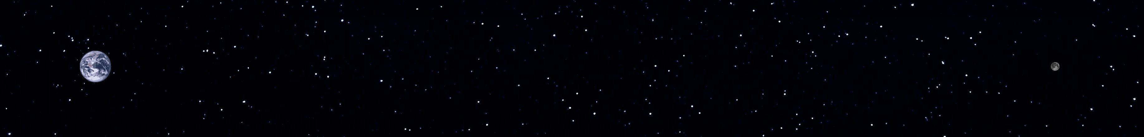
Earth and moon to scale
This is intended as a very basic introduction to the phenomena that affect an EME signal as it passes from the earth to the moon and back again. It's an overview, not a detailed explanation of what happens. No math is required (except perhaps for basic addition, subtraction, multiplication and division). Some degree of simplification is obviously required for a broad overview, but I've tried to keep things as accurate as possible. Any errors are all mine!
Geometry of the EME path
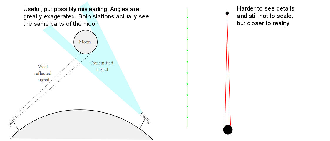
It's hard to get a realistic view of the geometry of the EME path. Most diagrams show the moon as being far too close to the earth, distorting the angles involved in the reflection of signals.
To get a realistic view of the earth moon system you'd need to stand off in space at a distance of at least 1 million miles. Luckily NASA have done this for us with their Osiris-Rex mission and they sent a picture of the earth-moon system as seen from deep space.
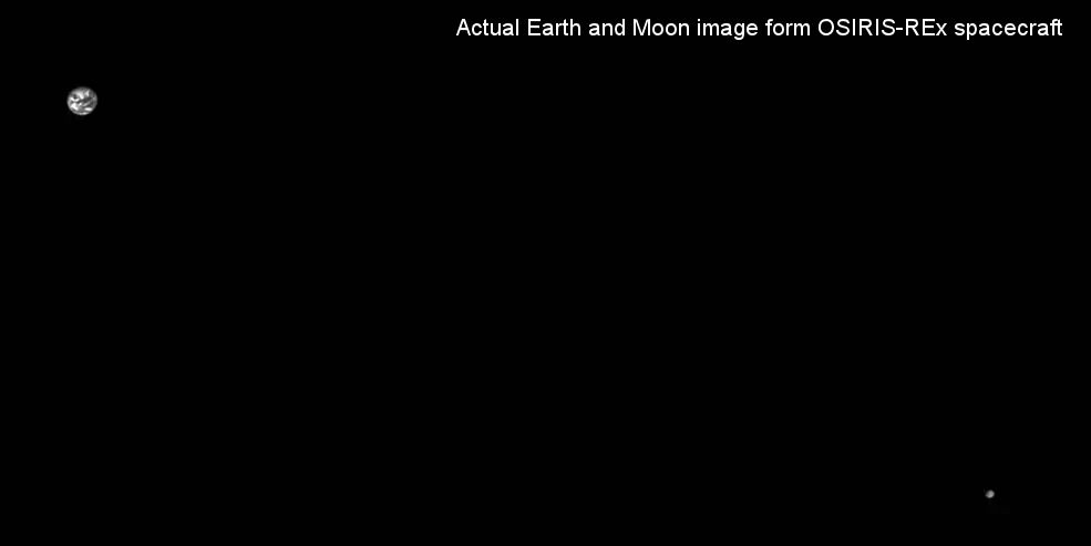
NASA has also made an animation of the system which shows the sizes and distances to scale together with an accurate animation of a signal passing between the earth and the moon.
The take-away from this is that all the signal which we see reflected back from the moon is almost a retro-reflection, i.e. a reflection back along the path of the incident signal. Anything that is reflected or scattered off to the side (by more than about 1 degree) misses the earth entirely.
Passage through the Troposphere
When a signal leaves the earth on a path towards to moon, the first thing it does is pass through the troposphere, a region up to about 50,000ft. This region contains 99% of the water vapor and is the region in which weather occurs. EME signals up to around 10Ghz are affected very little by weather and pass through the troposphere without any significant attenuation. However higher frequencies, such as 24 GHz and 47Ghz, can be absorbed by oxygen and water vapor, so they suffer from attenuation. Attenuation is least when humidity is low and the signal bath is toward the zenith and increases as humidity rises and the path moves towards the horizon.
Passage though the Ionosphere and Faraday Rotation
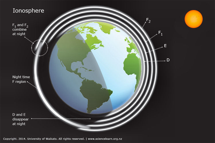
After passing through the troposphere, the signal then passes through the stratosphere (in which not much happens to it) and into the ionosphere, a region from about 48 km (30 mi) to 965 km (600 mi) above the earth. In this region, any remaining atmospheric gases (at very low pressure) can be ionized by solar radiation leading to the presence of free electrons. HF operators will be familiar with the D, E and F layers of the ionosphere, which can reflect RF signals up to 50MHz. However at 144 MHz and up these is no reflection from these layers. RF passes straight through them, but due to the presence of free electrons and the earth's magnetic field, the polarization of the signals is rotated due to the Faraday effect - this is Faraday Rotation.
The plane of polarization of signals can rotate as they pass through the ionosphere
The amount of rotation is a function of the frequency of the signal, the free electron density and the magnetic field. The Faraday rotation is inversely proportional to the square of frequency and directly proportional to the integrated product of the electron density and the component of the Earth's magnetic field along the propagation path. The consequence of Faraday rotations is that the plane of polarization of linearly polarized signals is rotated. The lower the frequency, the greater the amount of rotation. For example, at UHF frequencies (e.g. 432MHz), the signal usually rotates multiples times (720 degrees or more). If linear polarization is rotated by 180 degrees (or any multiple of 180 degrees) it will return to the same polarization as it started (vertical -> vertical or horizontal -> horizontal) but if the rotation is 90 degrees (or any odd multiple of 90 degrees, linear polarization will flip to the orthogonal polarization, i.e. from horizontal to vertical (or vertical to horizontal). Circularly polarized signals, whether left handed or right handed, retain their polarization when rotated. LHCP stays LHCP, RHCP stays RHCP.
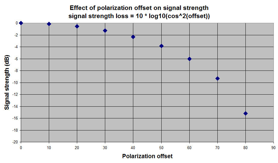
Faraday conversion of linear to circular polarization is also possible under the right conditions, but generally these conditions do not occur for EME signals. For EME only Faraday rotation is of concern. For linear polarization, a rotation of 30 degrees between the incoming signal and the antenna polarization will result in about 1.2dB of additional loss, while a rotation of 45 degrees results in about 3dB of additional loss. In practice the maximum loss with a 90 degree polarization difference will typically be something like 10 to 20dB (in theory the loss is infinite, but in practice polarization is never perfect).
The degree of Faraday rotation varies over time as conditions in the ionosphere change. The lower the frequency, the faster the rotation changes. It may rotate 180 degrees in a few minutes at 6m, while at 2m it may take 20 minutes and at 70cm it may take hours. If it's rotating fast, signals peak quite often so if signals are weak due to cross polarization you can wait a short while and signals may peak. This is fine for 6m and even 2m, but on 70cm you may have to wait hours for signal strength to change. There can be a small amount of rotation at 23cm and the rate of change is slow, but on 23cm EME almost everyone uses circular polarization, so Faraday rotation is not an issue. At 10GHz, linear polarization is common, but there is no Faraday rotation, so it isn't an issue there either.
If you are wondering why the polarization rotates, that's hard to explain without of lot of complex math (or in my case, waving of hands). One way to look at it is that linear polarization can be regarded as the superimposition of equal strength left and right circular polarization. The linear polarization angle is then given by the relative phases of the LHCP and RHCP components. When passing though the ionosphere, the earth's magnetic filed and the plasma (free electrons), the two opposite circular polarizations propagate with a different phase velocity, which then changes the polarization angle of the linear polarization which they produce. The plasma is said to be Gyrotropic and the phenomenon of the two circular polarizations having a different phase velocity is an example of birefringance.
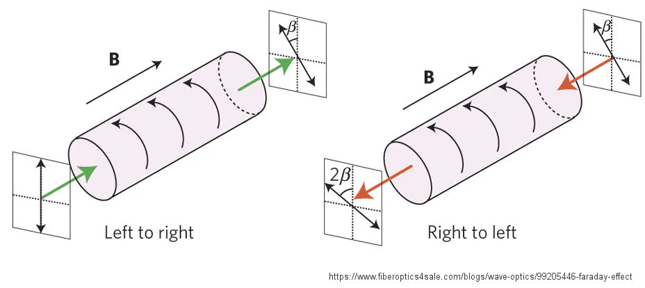
One very important (and perhaps non-intuitive) property of Faraday rotation is that the direction of rotation is the same no matter which direction the signal is traveling. So if you have 30 degrees of counter-clockwise rotation in one direction and then the signal is reflected pack and passes through the same zone of Faraday rotation again but in the opposite direction, it rotates another 30 degrees in the same direction, so the reflection ends up back at the source with 60 degrees of rotation.
Reflection from the moon
After passing through the ionosphere, nothing happens for the next ~ 1.25 seconds while the signal approaches the moon. The moon has no significant atmosphere, so the RF wave impacts the surface of the moon with no further modification. Since the moon is 3-dimensional, the signal hits the center of the moon about 5.8ms before it hits the edge. This gives rise to some time delay effects, so that some parts of the reflected signal can lag by almost 12ms after reflection from the moon. For the purposes of EME operation, this time spreading is of no significance.
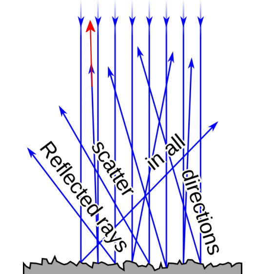
Only scattering/reflection back towards the earch (Red Arrow) contribute to the received echo
To be received back on earth, the signal reflected from the moon's surface must be reflected back within a fraction of a degree of the incident path. Any part of the signal that is reflected or scattered onto a path that isn't back directly towards the earth is lost. The earth presents about a 1.8 to 2 degree wide target as seen from the moon's surface. As you move away from the center of the lunar disk, the signal arrives at ever lower angles and this generally results in lower reflection back along the incident path. Basically, in terms of RF reflection, the center of the moon is brighter than the edges.
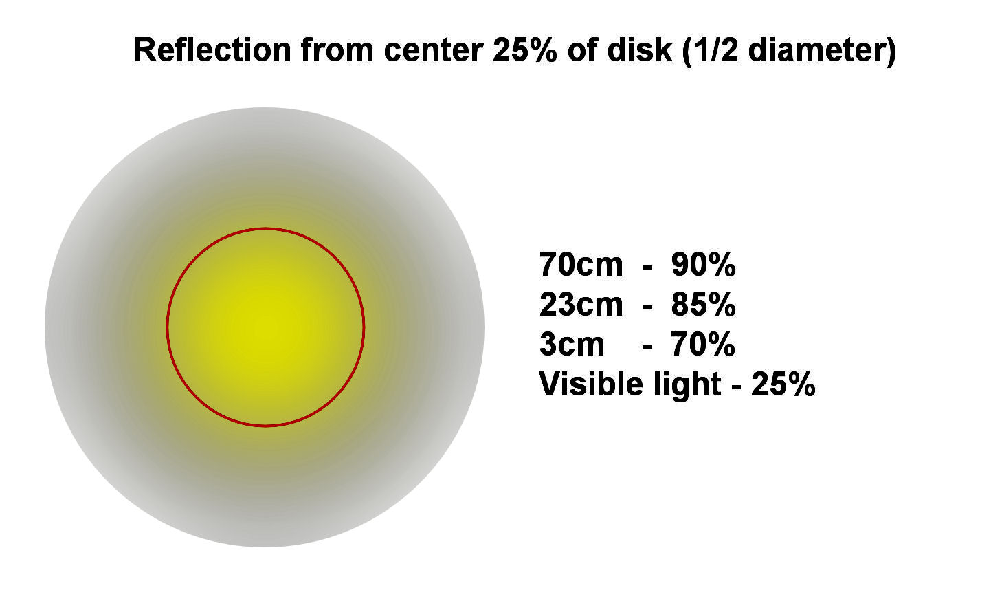
At lower frequencies most of the reflection comes from the central area of the moon. As the frequency increases the reflection is more uniformly distributed. As examples, at 70cm about 90% of the reflected power comes from the central 25% of the projected disk of the moon (1/2 the diameter). At 23cm this drops to about 85% and at 3cm to about 70%. This is in contrast to visible light where the center 25% of the disk area reflects about 25% of the visible light. This concentration of reflection towards the center of the disk is generally of no consequence form most EME operation, though could be something to consider on the higher microwave bands when the 3dB beamwidth of the antenna is smaller then the angular size of the moon (~0.5 degrees)
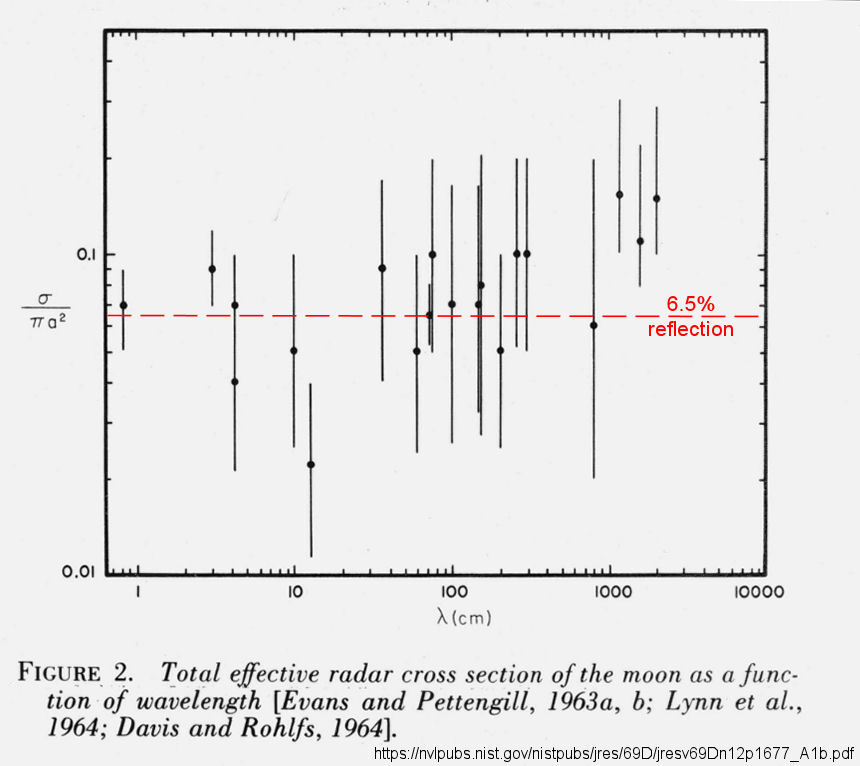
On average, the moon reflects about 6.5% of the incident RF energy
Doppler Shift
The Doppler effect. Wavelength is longer if the distance between the transmitter and receiver is increasing and sorter if the distance is decreasing
What is of considerable significance is the fact that the reflected signal frequency is Doppler shifted due to the changing distance between the transmitter on earth and the moon. When the source of the reflected signal is moving away from the receiver, the wavelength is lengthened and the frequency is lowered. When it's moving towards the receiver, the wavelength is shortened and the frequency increased. Almost all of the Doppler shift is due to the earth's rotation, not a change in the earth-moon distance.
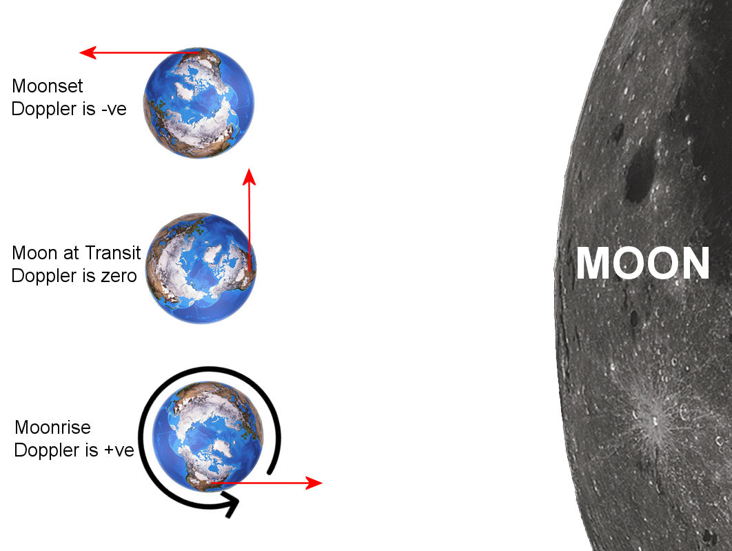
At moonrise, the rotation of the earth (~1000 MPH) is moving the Tx station towards the moon and so the Doppler shift of self echoes is positive (frequency is higher). When the moon reaches it's highest elevation (transit), there distance from the Tx station to the moon is at a minimum, the rate of change of distance is at a minimum (near zero) an so the self echo Doppler shift is near zero. From this point on the rotation of the earth carries the Tx station further from the moon, so the self echo Doppler shift becomes negative and the frequency is lower. When two stations are in QSO, the Doppler shift between then will depend on where on the earth's surface they are located. Both may see a (different) positive frequency shift, both may see a negative frequency shift, or one may see a positive shift while the other sees a negative shift. The maximum magnitude of the shift is a function of frequency. At 2m it may be +/- 330 Hz, at 23cm the range is +/- 3000Hz Hz and at 10Ghz it can be between +/- 24kHz. This means that on 2m EME you might get away without Doppler tracking singe all signals will likely be within the audio passband of the receiver, but at 23cm you need to compensate for and track Doppler shift and at 10Ghz unless you are compensating for Doppler shift and tracking it, you may never find the signal at all!
Libration Spreading and Fading
Of course the moon is not a flat disk, nor is it a uniform or smooth sphere, nor is it stationary. The surface difference in nature between the relatively flat "seas" (mare), craters with diameters from meters to 10s of km, and the mountains up to 18,000 ft, just as it does on earth. It's not uniformly reflective (in fact it's about 6.5% reflective on average), but the strength of reflection or scattering in the direction back to earth changes from place to place over short and long distances (cm to m to km). It also depends on angle of incidence and to a lesser extent, the frequency of the RF.
Lunar Libration as seen from earth
On top of all this, the moon is not a fixed disk (or sphere) in the sky. Though on average it mostly keeps one face towards the earth, as seen from earth it is actually in constant motion. This is known as Libration. The moon's surface is constantly moving with respect to an observer on earth (lunar libration). This means that the Doppler shift of echoes, along with the magnitude and phase of the reflected signal constantly changes. As you might guess, this can significantly affects the nature of the reflected signal.
One consequence of libration is that, due to the "rocking" component, one side of the moon will be rotating towards earth, while the other side is rotating away. The result of this is that the Doppler shift is slightly different from each side of the disk. In fact it's slightly different from each part of the disk. This is libration spreading.
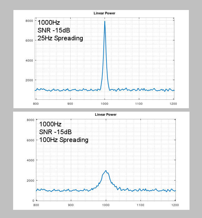
Difference between 25Hz and 100Hz spreading for a 1000Hz tone at -15dB (in 2500Hz bandwidth)
The effect of libration spreading on the Rx signal audio spectrum as received back on earth is to increase the width of the signal peak and lower its height. The area under the peak should remain constant, but the greater the spreading the harder it can be to tell the difference between the peak and the noise, especially at very low SNRs.
5Hz, 50Hz and 500Hz Libration spreading. These are 0dB SNR signals, VERY strong by EME standards
Another effect of libration is libration fading, where the strength of the echo can rapidly change (QSB) over time periods of a fraction to a second due to signals combining in and out of phase as well as the nature of the reflecting surface changing over small distance comparable to the wavelength. Both phenomena are frequency dependent. Spreading increases with frequency, as does the fading rate.
The echo of a constant carrier from the moon showing libration fading
There's a frequency range from about 432MHZ through 2.3GHz where the rate of QSB (1 to 10Hz)can be particularly problematic for CW since it approximates the symbol rate for typical CW speeds. In the worst case ,dots or dashes can be missing or a dash can be broken into two dots. There are times/frequencies for which one CW rate may be easier to copy than another.
Carrier at 700Hz and -8dB (2500Hz BW). A fairly strong signal by EME standards, Signal can be chopped up and sound like CW
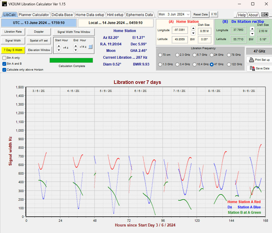
The program LibCalc can show libration spreading between any two stations at any time. Note the diferent values of libration spreading for stations A(red), station B (blue) and between station A and station B (green). at 47Ghz you can see that spreading ranges from about 400Hz to close to zero
Libration spreading can also make it harder to copy CW, especially on the higher bands since the signal can be spread over several hundred Hz, making sound more like an auroral "buzz" rather then a pure tone. Libration spreading also makes it more difficult for digital modes to decode. So, for example, the Q65 submode which gives the highest probability of a decode sensitivity needs to be chosen on the basis of the amount of libration spreading.
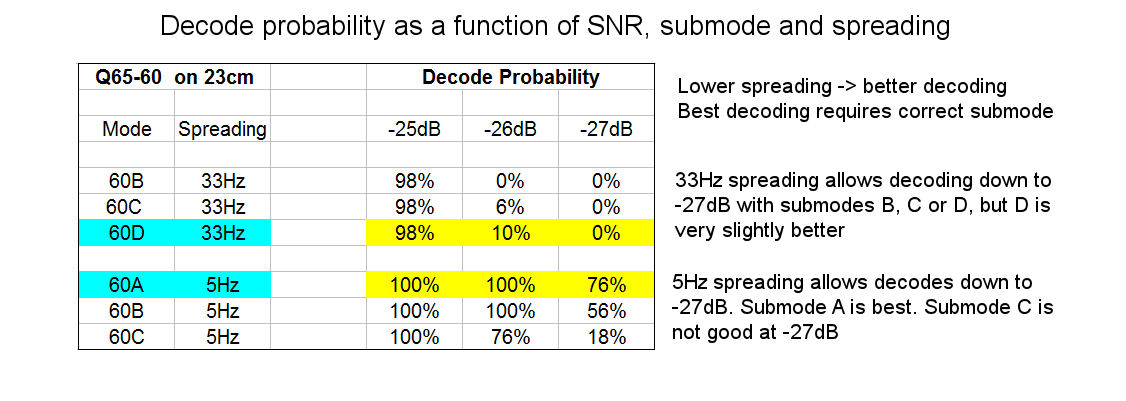
While submode 60A may usually be best on 2m, 60C maybe the best default choice for 23cm and 60D or 60E may be the best choice for 10Ghz, depending on the value of libration spreading at the time. WSJT reports the spreading value in its Astronomical Data window. When spreading is lowest and the correct submode is used, weaker signals can be decoded. Note that the degree of libration spreading for two stations A and B will be different for station A's self echoes, station B's self echoes and for the path between station A and station B.
Polarization Scattering
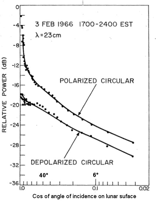
Depolarization as a function of angle of incidence on the lunar surface. When the incident signal is normal to the lunar surface (center of lunar disk), the depolarized com[ponent of the reflection in around 18dB down on the polarized component. When the angle of incidence is small (edge of the lunar disk), the depolarized component of reflection is only about 3dB on the polarized component (but the total reflected power from this region is low).
One further consequence of the reflection of the signal from the lunar surface is that the can be some degree of polarization scrambling. While most of the signals reflected back with a simple 180 degree phase change, which means horizontal linear comes back as horizontal linear, vertical linear comes back as vertical linear and Left Hand circular polarization comes back as right hand circular polarization, there can be a small fraction that comes back slightly rotated, or converted from circular to linear (and vice versa). In practice, this isn't a significant issue for EME operation. Most of the signal comes back with the expected polarization. Linear stays linear and circular stays circular (but the sense of rotation changes)
Back to earth and a second pass through the ionosphere
So at this point the signal is now on its way back to earth. The original narrow signal at the Tx frequency has been Doppler shifted, libration has resulted in spreading and fading and the polarization has been slightly scrambled, with LHCP converted to RHCP for circular polarization. Nothing significant happens to it the next 1.25 seconds or so until it hits the upper reached of the ionosphere. As it passes through the ionosphere it undergoes further Faraday rotation, which depends on the local electron density and magnetic field. If it's a self echo (Tx and Rx stations the same), the Faraday rotation will the in the same direction and with the same magnitude as the Faraday Rotation was on its outbound journey. So if it was linear and had a 30 degree rotation on its way to the moon, it will rotate a further 30 degrees in the same direction and arrive back at the antenna with a total of 60 degrees rotation. If the echo is received by a different station at a different location, it will be subject to the Faraday rotation present on that path (which will probably be different).
Passage through the troposphere will again have little effect on signals at 10Ghz and lower frequencies, but at 24Ghz and up there will be absorption by oxygen and water vapor.
Spatial (Geometric) Polarization offset - Dpol
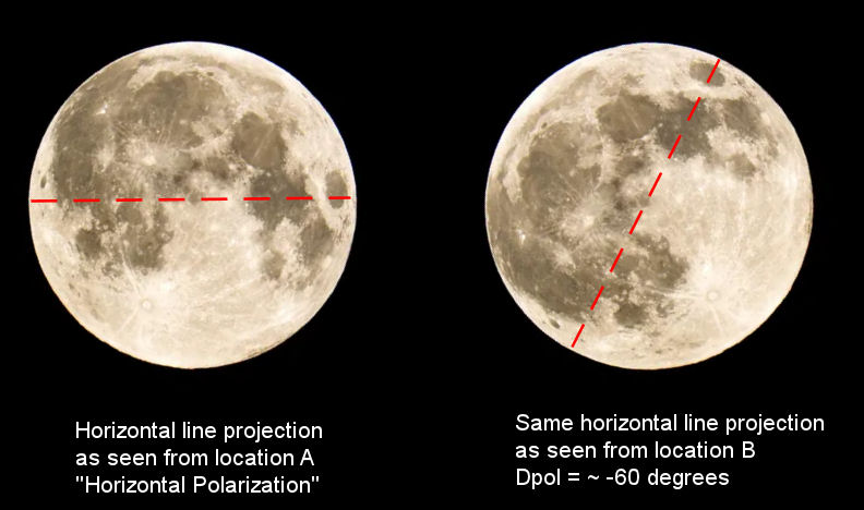
A final effect on the signal is that of polarization change due to the geometry of the earth-moon-earth path. This is known as geometric polarization offset, spatial polarization offset or Dpol (the symbol used in WSJTX). It occurs because linear polarization is measured with respect to the local horizon. For example, a horizontally polarized signal sent from California at moonrise and reflected from the moon will not be seen as horizontal when received by a station in Europe, where the moon is setting. In fact the spatial polarization offset between the central US and central Europe is often close to 90 degrees. Spatial polarization offset combined with Faraday rotation can, at times, result in a condition where station A can hear station B's EME signal perfectly well, but station B cannot hear station A, even when both stations are using the same antenna and transmit power. On the other hand, at times the spatial polarization offset can cancel out Faraday rotation, resulting in the maximization of the received signal.
EME path loss
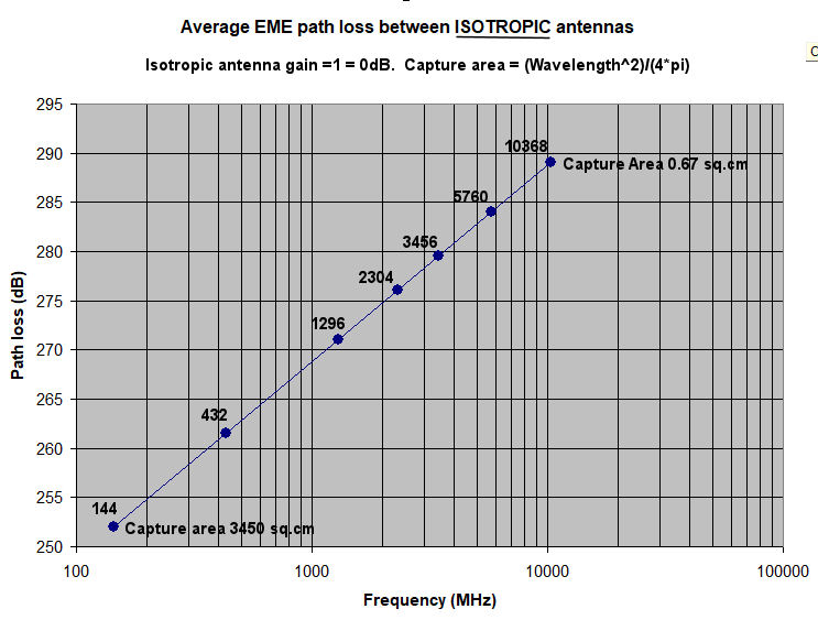
You will notice that (apart from absorption by the atmosphere at 24GHz and up), I have not mentioned any signal absorption due to the distance from the earth to the moon and that's because there isn't any absorption in a vacuum. Free space does not absorb electromagnetic waves unless there is something in it (like gas clouds, which do exist in places in space). If free space absorbed RF there would be no radio astronomy and you wouldn't see many stars! So when you see a chart of "Path Loss vs Frequency" for EME operation, what's going on. Why is the path loss at 144MHz shown as 37.15dB higher than the path loss at 10368 MHz? It's certainly not due to any kind of absorption.
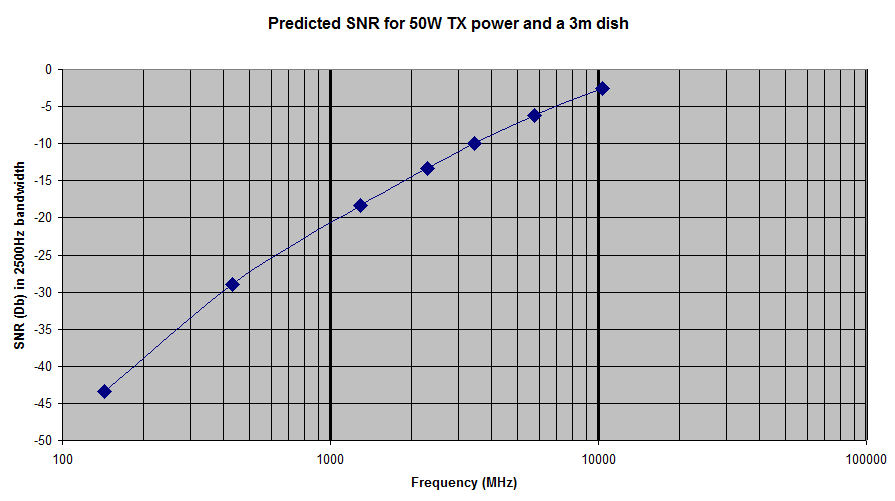
The answer is that those path loss plots are for isotropic antennas, i.e. antennas with a 0dBi gain. The amount of energy captured by an antenna is a function of its capture area, which for an isotropic antenna is (wavelength^2) / (4*Pi). For 144MHz an isotropic antenna is capturing signal falling on an area of 3450 sq.cm, while at 10368 MHz, and isotropic antenna is capturing energy from the signal falling on 0.67 sq.cm. Hence the huge (37.15dB) difference is EME loss vs frequency for isotropic antennas. However nobody uses isotropic antennas for EME! The inequality of the bands is therefore not as much as the simple "path loss vs frequency" plots for istropic antennas may initially suggest. Two stations running 2.4m dishes and 150W on 23cm will see approximately the same strength signals as two stations running 1.8m dishes and 25W at 10GHz. However, at 10Ghz the antenna will have to be more accurately profiled and pointed more accurately, plus 25W on 10Ghz will cost significantly more than 150W on 23cm, so all is not equal. The graph shows the expected Rx SNR for a station running 50W and a 3m dish antenna from 2m to 3cm. This is a bit unrealistic in practice, but it shows that under these conditions, the higher the frequency of operation, the stronger the signal.
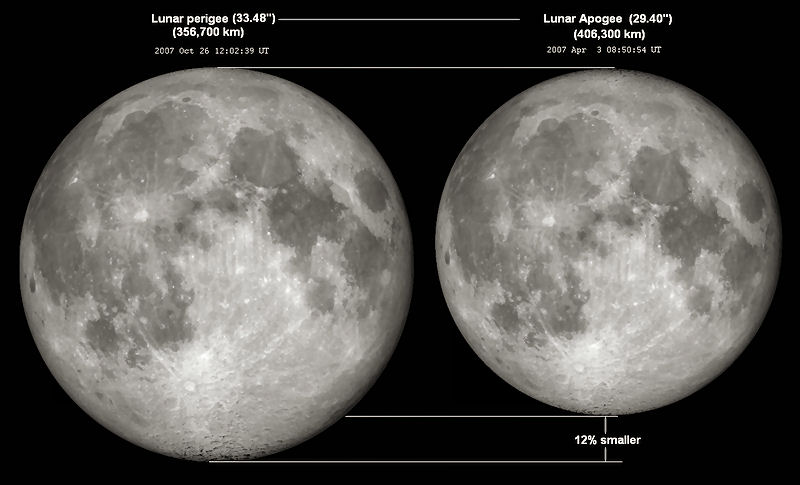
Path loss also changes with the distance of the moon. at it's closest (perigee) loss is about 2dB less than when the moon as at its maximum distance (apogee) due to geometric changes in the path. When trying to work weak stations, this is certainly a factor to take into consideration. WSJTX reports the added loss due to the moon being further away then perigee in its Astronomical data window as DGRD (degradation) and the value runs from about 0dB to about -2.1dB
Sky (and other) Noise
The moon's path across the sky passes in front of Sagittarius A (the galactic center) where noise is high, then about 8 days later it passes in front of the sun (where noise is high again) and a 8 more days it moves into the constellation of Leo, where background noise is low. The regions of high and low noise are similar at 2m and 70cm. At 23cm and up noise is low across whole sky
One final factor related to EME signal detection is the amount of noise the antenna sees when pointing at the moon. Most EME systems have a beamwidth larger then the moon, so that in addition to an EME signal reflected of the moon, the antenna sees any signals coming from an area around the moon. There are noise sources out in deep space and these can be an issue on the lower EME bands (below 23cm). There are quiet and noisy areas of the sky and EME signals will be easiest to detect when the moon is in front of a quiet area. I should mention that on the higher microwave bands, such as 10,24 and 47GHz, where beamwidths are closer to (or smaller than) the diameter of the moon, the moon itself is a source of excess noise. This is thermally generated noise but is typically not detectable with most EME systems at 2m, 70cm and 23cm. The sun is also a very strong noise source, so with antennas having a wide beamwidth EME will be very difficult when the moon is close to the sun in the sky (new moon). On higher bands with narrow beamwidths EME contacts can sometimes still be made around the time of new moon.
Summary
The physics and geometer of the EME path tell us a number of things about what to expect on various different bands and indicates what needs to be done to maximize the decoding of signals (whether CW or digital). The Q65 digital mode of WSJTX is optimized for the decoding of signals which show the characteristics of the EME path. JT65 (an earlier encoding scheme) was also written with the characteristics if the EME path in mind.
- Polarization - Due to Faraday rotation and spatial polarization offset, on the bands below 23cm the linearly signal reflected from the moon will return with some degree of polarization rotation. At time signals will return with the same polarization as sent and so there will be no additional loss. At times signals may return with orthogonal (90 degree) rotation and so will be very weak. The solutions are: (a) wait for Faraday rotation to change or (b) use some sort of adaptive polarization receiving system.
- Doppler Shift - Lunar echoes will return with a Doppler induced frequency shift. At 2m The shift is a few hundred Hz and so you may not need to compensate. At 23cm signals may be shifted by up to a few kHz and change at a rate of 10Hz/minute, so Doppler compensation is required and Doppler tracking (changing frequency in real time) is highly desirable. At 10Ghz, the Doppler shift can be 10s of kHz and the rate of change can be 1Hz/second, so Doppler compensation and accurate Doppler tracking is required.
- Libration - Lunar echoes will be broadened, from a few Hz at 2m to a few hundred Hz at 10Ghz. On the lower bands this isn't really an issue. On the higher bands (23cm and up), the choice of the Q65 submode which best matches the libration spreading and result in several dB of increased detection sensitivity. Libration fading always present and there's really nothing you can do about it
- Path loss At perigee signals may be 2dB stronger than at Apogee. If dealing with very weak signals, schedule you contacts for the times of minimum loss.
- Sky Noise At 432MHz and lower frequencies, signals will be easier to detect when the moon is in a quiet part of the sky (and well away from the sun).
- Weather Unless you are operating at 24Ghz and above, don't blame the weather for weak signals!
References
- "Frequency-Dependent Characteristics of the EME Path" - Joe Taylor K1JT https://wsjt.sourceforge.io/EME2010_K1JT.pdf
- "High-Accuracy Prediction and Measurement of Lunar Echoes" - Joe Taylor K1JT https://wsjt.sourceforge.io/LunarEchoes_QEX.pdf
- "Libration" - WikiPedia https://en.wikipedia.org/wiki/Libration
- "Polarization and "One-way" EME Propagation" http://www.ifwtech.co.uk/g3sek/eme/pol4.htm
- "RADAR PR0PERTES OF THE MOON" Tor Hagfors https://ntrs.nasa.gov/api/citations/19670004927/downloads/19670004927.pdf
- "A study of the depolarization of lunar echoes" Tor Hagfors, https://ok2kkw.com/eme/%C3%ADndex.htm/moon_mechanics_&_properties/depolarization_of_lunar_echos.pdf
- "EME Link Budget & Analysis Tool (1 - 300 GHz)" Gerald Ihninger, OE2IGL https://wettersat.bplaced.net/EME/EME.htmlM
- "Waves in Gyrotropic Media,Polarization" https://engineering.purdue.edu/wcchew/ece604f20/Lecture%20Notes/Lect9.pdf
- WSJTX User Guide (2.7.0-rc3)
- Q65 Quick Start Guide
- EMECalc EMECalc by VK3UM (SK). Does just about every EME calculation you will need, plus moon and sun coordinates for past, present and future. An indispensable program for EME work.