.jpg)
SMA Connector Loss at 1.3 GHz - Literature Summary
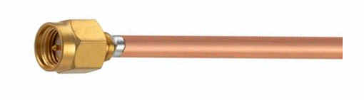
While "a rose is a rose is a rose" it's not true that an SMA connector is an SMA connector, i.e. just because connectors appear to look the same, it doesn't mean their RF performance is the same. SMA is a physical size specification, not an RF performance specification. A high precision laboratory grade SMA connector tested and rated to 18GHz will no perform the same as a Chinese SMA connector from Aliexpress which (assuming accurate specifications are provided) may not be rated to more than 3Ghz. Even at 1.3Ghz (23cm), their performance (loss, vswr) will differ. Cost will differ too, sometimes by a factor of 50x or more!
Scope: This short summary separates published measurement evidence from manufacturer specifications. The emphasis is on 50-ohm SMA connectors and adapters around 1.3 GHz, with particular attention to mating repeatability and the effect of repeated mating.
1. What the literature supports
There is good metrology literature on SMA connector repeatability, but much less published data giving a statistically representative absolute insertion loss for large populations of SMA connectors. The most useful direct experimental studies are R. L. Jesch (1976), "Repeatability of SMA Coaxial Connectors," and A. J. Estin (1976), "Scattering Parameters of SMA Coaxial Connector Pairs." Both appeared in IEEE Transactions on Instrumentation and Measurement. NIST bibliographies identify both papers as microwave-metrology references.
Bergfried and Fischer (1970) made particularly useful life tests. They measured mated connector pairs, including SMA, through 10,000 connect/disconnect operations, at 2,500-cycle intervals, over 2-18 GHz, with a stated measurement resolution of 0.0001 dB. For new connectors, the standard deviation of insertion-loss repeatability ranged from below 0.002 dB for the best connectors to 0.008 dB for the worst tested. After 10,000 connections the standard deviation increased by as much as a factor of three. These are repeatability figures, not the absolute insertion loss of the connector.
The NPL/ANAMET Connector Guide gives practical uncertainty figures based on experience at NPL, SESC and UKAS calibration laboratories. For SMA/3.5-mm connectors it gives approximately 0.002 dB repeatability from DC-1 GHz and 0.006 dB from 1-12 GHz, provided the connectors are clean, mechanically sound, correctly mated, and not subjected to transverse loads or misalignment.
2. Reasonable loss at 1.3 GHz
Published manufacturer specifications provide a useful engineering range, although they should not be confused with independent population measurements. Several reputable SMA specifications use limits of approximately 0.03 to 0.06 times the square root of frequency in GHz, per connector. At 1.3 GHz this corresponds approximately to:
- 0.03 sqrt(f): 0.034 dB per connector, or about 0.068 dB for a pair.
- 0.04 sqrt(f): 0.046 dB per connector, or about 0.091 dB for a pair.
- 0.05 sqrt(f): 0.057 dB per connector, or about 0.114 dB for a pair.
- 0.06 sqrt(f): 0.068 dB per connector, or about 0.137 dB for a pair.
These figures suggest that about 0.07-0.10 dB for a good SMA mating pair at 1.3 GHz is a reasonable engineering expectation. A value around 0.10 dB per pair is a conservative assumption for a good commercial connector pair. Published specifications should not be interpreted as evidence that every connector pair actually has that loss.
3. Straight versus right-angle SMA
Right-angle connectors can have somewhat greater loss and/or poorer return loss than equivalent straight connectors because the RF path has to negotiate the bend. The difference is design-dependent rather than a universal property of the SMA interface.
For example, a Fairview Microwave cable-assembly specification estimates the loss of its SMA right-angle connector as 0.04 sqrt(f) dB maximum. At 1.3 GHz that is about 0.046 dB per connector. Norsat specifies 0.05 sqrt(f) dB for an SMA right-angle connector on one of its high-performance cable assemblies, or about 0.057 dB at 1.3 GHz.
Older SMA specifications also show that right-angle cable connectors can have higher specified insertion loss than straight versions. Consequently, for a precision 1.3-GHz measurement, a straight connector is generally preferable when the mechanical arrangement permits it, but a well-designed right-angle SMA need not introduce a large loss.
4. SMA adapters
An SMA-to-SMA adapter is not necessarily equivalent to simply adding one ordinary connector interface. The adapter contains its own coaxial transition and two mating interfaces, so its specified insertion loss depends strongly on its construction.
Published commercial specifications span a fairly wide range. For example, HASCO specifies no more than 0.04 sqrt(f) dB for one high-quality SMA female-to-female bulkhead adapter, corresponding to about 0.046 dB at 1.3 GHz. A Mini-Circuits SMA female-to-female adapter is specified at 0.1 dB typical over DC-18 GHz. Other commercial adapters are specified around 0.15-0.2 dB maximum, while some high-frequency precision adapters have still higher broadband specifications.
Thus an adapter should be treated as an individual RF component rather than assigning it a universal "one SMA pair" loss. For a 1.3-GHz EME system, measuring the actual adapter with a VNA is preferable when differences of a few hundredths of a dB matter.
5. What happens after 100 mating cycles?
The published life-test literature does not support a reliable universal number such as "100 matings add 0.02 dB." The major published experiments generally measured at much larger intervals. Bergfried and Fischer tested at 2,500-cycle intervals up to 10,000 cycles. Their results show increasing repeatability variation with use, but do not establish a simple linear increase in average insertion loss with mating count.
Modern SMA specifications commonly require hundreds of mating cycles; 500 cycles is a common durability requirement. Therefore 100 properly performed matings should not, by itself, be assumed to produce a large loss increase in a good-quality connector. Connector cleanliness, alignment, correct torque, mechanical loading, plating condition and damage can be more important than the simple number of mating cycles.
6. What can reasonably be concluded for a 1.3-GHz EME system?
- A good SMA pair at 1.3 GHz is plausibly in the 0.07-0.10 dB range, but this is an engineering expectation derived largely from specifications, not a statistically established universal measurement.
- Values around 0.1 dB per connector sometimes appear in commercial cable specifications; these are often conservative allocation figures and should not automatically be interpreted as measured interface loss.
- Good SMA connector mating repeatability can be only a few thousandths of a dB. This is why careful connector technique matters when attempting to infer very small losses from VNA or Y-factor measurements.
- There is strong evidence that repeated mating eventually increases repeatability uncertainty, but insufficient evidence to assign a fixed additional loss after exactly 100 cycles.
- Right-angle connectors can have somewhat higher loss than straight connectors, but good designs can still be only about 0.05-0.06 dB per connector at 1.3 GHz.
- SMA adapters vary considerably by design. For measurements where 0.01-0.05 dB matters, the actual component should be measured rather than assigned a generic loss.
References
- D. Bergfried and H. Fischer, "Insertion-Loss Repeatability versus Life of Some Coaxial Connectors," IEEE Transactions on Instrumentation and Measurement, Vol. IM-19, No. 4, pp. 349-353, Nov. 1970. DOI: 10.1109/TIM.1970.4313926.
- R. L. Jesch, "Repeatability of SMA Coaxial Connectors," IEEE Transactions on Instrumentation and Measurement, Vol. IM-25, No. 4, pp. 314-320, Dec. 1976. DOI: 10.1109/TIM.1976.6312234. NIST bibliography entry: NIST microwave-metrology bibliography.
- A. J. Estin, "Scattering Parameters of SMA Coaxial Connector Pairs," IEEE Transactions on Instrumentation and Measurement, Vol. IM-25, No. 4, pp. 329-334, Dec. 1976. Listed in NIST microwave-metrology bibliographies.
- NPL/ANAMET, ANAMET Connector Guide, Appendix C, "Repeatability of Connector-Pair Insertion Loss." The guide states that its figures are based on practical measurement experience at NPL, SESC and UKAS calibration laboratories.
- Fairview Microwave, SMA right-angle cable assembly specifications, including the stated estimate of 0.04 sqrt(f) dB maximum for the SMA right-angle connector.
- Norsat, low-loss phase-stable cable specifications, including 0.05 sqrt(f) dB insertion loss for specified SMA right-angle connectors.
- HASCO Components, SMA female-to-female bulkhead adapter specification: no more than 0.04 sqrt(f) dB insertion loss.
- Mini-Circuits, ZT-314D SMA female-to-female adapter panel specification: 0.1 dB typical insertion loss per adapter over DC-18 GHz.
Important: The literature is much stronger for connector repeatability than for a universal absolute SMA insertion-loss value. The often-quoted 0.07-0.10 dB per pair at 1.3 GHz should therefore be regarded as a practical engineering estimate, not as a measured standard value applicable to every SMA pair.