.jpg)
Linearity and Measuring Sun Noise
Accurate sun noise Y-factor measurements depend on one thing above all: your measurement system must be linear. This page explains why that matters, how nonlinearity shows up and distorts your readings, and how to check for it and fix it. (Other pages on this site cover the underlying theory and detailed measurement procedures - this page focuses on why linearity is the thing to get right.)
The basic requirement for measuring sun noise is that you measure some signal which is linearly proportional to the RF energy captured by the antenna. What you measure doesn't matter. It can be the audio output power of a receiver in the standard audio bandwidth (typically something like 2.5kHz, e.g. from 400Hz to 3000Hz). It can be the "audio" power in the output from a wideband SDR like a FunCube Pro+ (a bandwidth of maybe 90kHz) or it can be a specialized wideband RF receiver covering several MHz. Whatever system you use, a 10dB change in the power received by the antenna must translate into a 10dB change in the final reading. A 1dB change in RF should have a 1dB change in final reading. If you have very high levels of sun noise (big dish) you might need linearity over a 20 or 25dB range.
You don't get good linearity over a wide range by accident. You have to make sure that none of the amplifiers (RF or audio) is going into compression. And of course, if measuring at the audio output of a receiver, you must make sure that any AGC in the receiver is turned OFF.
If you do not have a linear system, you will not get an accurate measure of sun noise (typically it will read lower than it really is).
Compression
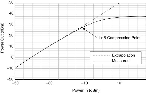
Here is an example of nonlinearity. For a 60dB change in the input signal, a linear amplifier would produce a 60dB change in the output signal, but it doesn't. Here a 60dB change in the input results in about a 47dB change in the output. If you were measuring sun noise and the true value was 60dB (a VERY big dish...), you'd only measure it as 47dB if your amplifier chain behaved like this. The higher the initial power input, the less additional power it takes to go into compression. In the example above, with -10dBm input power you are already in compression and have no upward dynamic range of linear operation.
A typical EME system has multiple amplifiers. Typically a 2 stage amplifier at the feed (LNA), then, if using a transverter, there's an amplifier at the RF input and an amplifier at the IF output. Then in the IF receiver (rig) there's another amplifier at the input. Probably some more amplifiers in various stages depending on the receiver design, and finally an amplifier at the AF output. Each and every stage of amplification must be linear in order to get an accurate sun noise reading.
For an amplifier to operate in the linear mode, you have to control the gain and the signal level presented to it. Hopefully the LNA, transverter and rig designers have done their best to keep things linear, given appropriate input levels. A sure way to drive an amplifier into compression is to feed a signal into it that is too strong, or to have too much gain so that the output is driven into a non-linear region.
Keeping Things Linear
The first thing to do is to see if your system is linear, and measure over what range linearity is maintained (dynamic range). Then if it isn't linear over a wide enough range, modifications may need to be made to the input level and/or gain of some of the amplifier stages. What you want to see is a situation in which if the signal being imput the the system changes by 10dB, the the output from the system (i.e. the audio output power) would also change by 10dB. Indeed, the ideal would be that however the input was changed, the output would be 1inearly proportional to it.
You might think that if you just put a 10dB attenuator ahead of the radio, then the output should change by 10dB, but that's not generally the case. It's a bit more complex then that.
Why Attenuation Ahead of the Rig Doesn't Come for Free
The basic reason why adding an attenuator ahead of the radio to measure linearity (or sun noise) can be misleading is that an attenuator doesn't just reduce signal, it also adds its own noise. Thinking in terms of noise temperature (which is directly related to noise power), if you add a 10dB attenuator between a noise source and a receiver, you lower the noise temperature of the source by 10dB, but you also add in the noise temperature of the attenuator itself.
So if you have a source at a noise temperature of 2000K (typical for sun noise from a 3m dish) and you put it through a 10dB attenuator, the noise temperature of the source is reduced to 200K, and the noise power from the source is lowered by 10dB. However, a 10dB attenuator that is physically at 290K (17C) itself has a noise temperature contribution of 2,610K. So adding a 10dB attenuator at that point can actually make the received noise power go UP, from 2000K to 2610K - not exactly what you were expecting.
However, it's not quite as bad as this might make it seem, if the attenuator is placed after a high gain, low noise, LNA. If you have an LNA with a gain of 35dB and a noise figure around 0.25dB, that 2000K noise temperature increases to about 6,324,555K. Now if you add 10dB of attenuation, that drops by a factor of 10 to 632,435K. The 2610K noise contribution of the 10dB attenuator then becomes insignificant by comparison, and the total noise temperature is 635,066K - the signal has effectively been attenuated by 9.98dB, very close to the true 10dB. This is basically an application of the Friis formula for noise in cascaded amplifier chains: as long as you have enough gain ahead of an attenuator, adding it won't meaningfully hurt your system noise figure or your linearity or sun noise measurement. The key is that you need significantly more gain in the LNA than you add in attenuation. This matters most when the source temperature is low, for example the antenna temperature when looking at cold sky - this can be 25K or even lower on the microwave bands, depending on spillover and losses ahead of the LNA.
The table below shows how close the measured attenuation gets to the true attenuation, for a system with a 0.25dB NF LNA (35dB gain is typical for a modern 2-stage LNA; a 3rd stage, after line, filter and splitter losses, might bring effective gain to about 45dB). Each column is a different amount of attenuation added at the input; each cell shows the resulting change in output noise power that you would actually measure, versus the attenuation dialed in. Note these are the net RF gin from the LNA input to the rig (or attenuator). If the LNA has 35dB gai, but you have 10dB line loss, the net LNA gain is only 25dB.
Measured dB drop in output noise, for a given amount of attenuation added at the LNA input:
T-source	LNA 	10dB	20dB	30dB
2000K	       35dB	10.00	19.98	29.81
50K		35dB	9.95	19.45	26.27
25K		35dB	9.92	19.15	24.99
25K		45dB	9.99	19.91	29.15
The takeaway: you can measure Y-factors for things like sun noise using an attenuator ahead of your rig or transverter, and you can use the same technique to measure system linearity, as long as the amount of attenuation you use is modest, you have enough gain between the LNA and the attenuator, and the attenuator itself is calibrated and matched with 50 ohm inputs and outputs. With 35dB of net gain, a 10dB attenuator at the input to the RF system should give about a 9.92dB change in audio output power. With 45dB of net gain, a 10dB input attenuation should give a 9.99dB change in audio output power for a linear system.
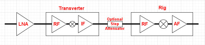
Above is a typical system configuration. There's an LNA at the antenna with one, or more often two, amplifier stages. There's typically no gain adjustment on the LNA, but it's designed to be linear unless it's grossly overloaded with signal (and EME signals are so low that they don't overdrive anything!). This feeds into a transverter, which has an RF gain stage, a mixer and an IF gain stage. In some transverters the gain of these amplifiers can be adjusted. The IF output from the transverter (often at 144MHz) is then fed into the input of the rig. This can be done via a step attenuator for measurement purposes, as described below. The rig usually has an adjustable RF amplifier (RF Gain control). The RF then goes through some sort of mixer (or SDR equivalent) and then into the final AF amplifier (which has adjustable gain). The audio power can then be measured, usually via a computer sound card and appropriate software (WSJT-X in Echo mode, SpectraVue or similar programs).
Checking Linearity with a Step Attenuator
If you know your transverter is linear (which is likely the case), the easiest way to measure overall linearity is to use a variable step attenuator between the transverter and the rig. Let's say you put a 20dB step attenuator there, whose value can be adjusted in 1dB steps. You could use a set of fixed attenuators (or even just one, as described later), but a step attenuator makes it easier and gives you a bit more information. The additional gain of the transverter should isolate the system from changes in noise figure due to the attenuation.
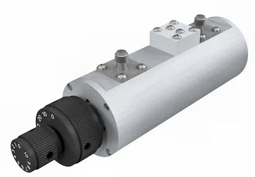
Wide range step attenuator with 1dB steps, 0-60dB, 0-2700MHz
First you set the attenuator to 0dB. Next you point the antenna at the cold sky and take a noise level reading. Call this Nc (Noise Cold). You then point the antenna at the sun and take a second reading. Call this Ns (Noise Sun). Now you increase the attenuation by 1dB. Your noise power should decrease by 1dB if you have a linear system. Then you increase the attenuation to 2dB, 3dB and so on until you get back down to a noise level that's the same as the original cold sky noise (Nc). Now you compare the attenuator reading (let's say it's 10dB) with the reduction in noise power. If it's also 10dB, you have a linear system, with at least a 10dB dynamic range. If there's only an 8dB drop in noise power, your system isn't linear. The attenuator (assuming it's properly calibrated) gives you your true sun noise (10dB). Your non-linear system, measuring audio noise power, only gives you 8dB.
IMPORTANT NOTE: Step attenuators (in fact almost all attenuators) are calibrated for use in a 50 ohm line. If not used with 50 ohm impedance at the input and output, they will not give the attenuation they are marked with. To be safe you may want to add a 3dB fixed 50 ohm attenuator before and after the step attenuator. See Attenuator Mismatch Losses.
So now what? The first thing to try is lowering the RF gain of the rig. That's the most likely place for excessive gain, because it's not really designed to operate with a bunch of amplifiers ahead of it - it's made to be sensitive and amplify very weak signals. So turn down the RF gain a bit and repeat the measurement sequence. Maybe this time you get 10dB again from the attenuator, but 9dB from the audio power measurement. Better, but not quite there yet. Turn down the RF gain a bit more and try again. This time you may get 10dB from both the attenuator and from the AF power measurement. You're now good to go - at least for a 10dB dynamic range. Your AF power measurement agrees with your attenuator measurement.
If you can't get linearity, it's possible (but unlikely) that some stage of the transverter is going into compression. If you can adjust gain there, try it. You could probably even put an attenuator ahead of the transverter and not increase your system noise figure, but too much attenuation between the LNA and transverter will raise the system noise figure and make weak signals harder to hear, so don't try this unless you know what you are doing!
Fixed Attenuator Method
For a lower cost and a single point measurement, you can use a single fixed attenuator, e.g. 10dB, 15dB or 20dB. If you put that in the IF path, audio power should drop by 10dB, 15dB or 20dB. If it drops by less, you're non-linear and probably going into compression, so lower the RF gain and try again.
Electronic / Digital Attenuators
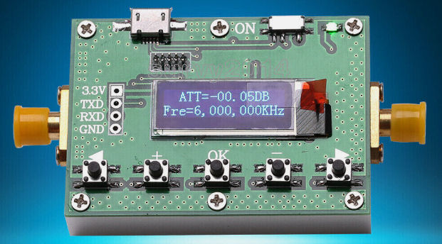
There are also micro-controller controlled digital attenuators based on chips like the Analog Devices HMC472A (chip specs below). They need power to operate, but are inexpensive, many in the $20-40 range. You can find them on eBay and sites like AliExpress. They probably work OK but I have not used one. There are also devices based on the PE4302 chip (obsolete now, but used in many Chinese boards). It gives 0-31.5dB in 0.5dB steps. Again, this requires power of course.
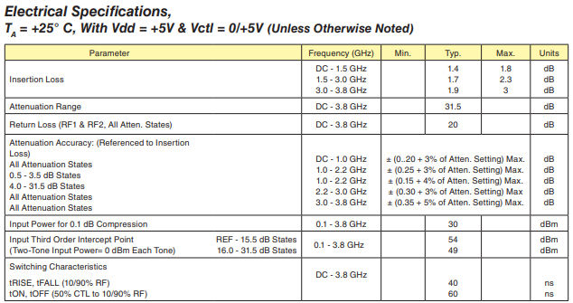
Obviously, all these measurements depend on the attenuator being properly calibrated and well matched at the frequency of use. The precision of step attenuators is typically +/- 0.5dB. If you want something better than that, it's going to be very expensive. Even quality small SMA fixed attenuators are typically only accurate to around +/- 0.5dB over most of their range, though slightly better, +/- 0.3dB, for low attenuation (1-3dB) - that's the spec for Amphenol SMA attenuators, for example. You can probably pick up a used 0-30dB 1dB step attenuator on eBay or similar sites for something under $50. There are cheap Chinese push-button step attenuators (rather than the rotary type). They are a bit cheaper but I'm not sure I'd trust them. They are rated to 3GHz, but the specs (which are often inaccurate on Chinese parts, and not in a good direction) are given as "Single-button attenuation accuracy: 0-8dB ±0.9dB / 10-20dB ±2.0dB / Multi key accuracy (>20dB) ±3.5dB" - which is not at all impressive. Insertion loss is <= 3.5dB. I wouldn't trust it.
You can also tweak the gain of the transverter if it has that capability. Instead of adjusting the RF gain of the radio, you could adjust the IF gain of the transverter. You're doing much the same thing here - lowering the power output of the RF stage in the rig, either by feeding it less signal or lowering the gain.
Testing Over a Wider Dynamic Range
If you want to test the system over a wider noise range you are going to need a stronger noise source than the sun, typically an RF noise generator. You could feed this into the attenuator in place of the IF signal. Adjust the noise level with attenuators until the noise matches Nc (noise from cold sky), then decrease the attenuation by 25dB. This will simulate 25dB of sun noise! Again, by adjusting the attenuator and looking at the audio noise power measurement, you can see if things are still linear. If they are not, turn down the RF gain until they are, then repeat the sun noise measurement and make sure it is still linear.
You can turn the RF gain down too far - this is obvious because if you turn it all the way down, you won't get any RF output. You don't really need much more dynamic range than you expect to get from the actual sun: 20dB would be more than enough for a 3 or 4m dish at 1296MHz. If you have a 10m dish you might need 30dB dynamic range, but you might not get it. In that case you can always make the measurement using the attenuator in the IF line rather than using noise power, or use a real RF power meter with a narrowband filter at the IF output of the transverter - though that's getting more complicated.
What if you don't have an attenuator?
If you don't have an attenuator and want to see if you are in the linear region when measuring sun noise using the audio output of your rig, you can do the following, using whatever audio noise level measurement system you have (e.g. WSJT-X in Echo mode or SpectraVue looking at the rig's audio output). This technique is best for an RX system that doesn't use a transverter, since it then establishes that the whole system is linear. If you use a transverter, you can still do this to confirm that everything after the transverter is linear - most transverters are likely to be linear but that isn't 100% certain.
- Measure the cold sky noise level (Nc)
- Measure the noise level pointing at the sun (Ns)
- Nc - Ns gives you your Y-factor sun noise (Sn)
- Reduce RF gain by 3dB
- Repeat #1, #2, #3, #4 - this gives you Sn(2)
- Reduce RF gain by another 3dB
- Repeat #1, #2, #3, #4 - this gives you Sn(3)
- Reduce RF gain by another 3dB
- ...keep going until sun noise starts to drop again...
If you were not initially in compression, you should see constant sun noise as you reduce RF gain, up to a point at which sun noise starts to drop.
If you were initially in compression, you will see sun noise rise when you reduce RF gain, then it will level off as RF gain is reduced a little more, and finally it will drop as RF gain is lowered further.
If sun noise drops as soon as you reduce RF gain from its maximum setting, you don't have enough gain ahead of the rig - this could be an LNA with insufficient gain, or a cable from the LNA with too much loss.
You want the RF gain setting that puts you in the "flat" region of this data set. You probably want to be just above the point at which decreasing RF gain starts to make the calculated sun noise start to fall.
Note that the RF gain control is not usually equivalent to and external attenuator on most modern rigs, It does not control the gain of the first RF stage in the radio. For example, in the Icom IC-9700 direct-sampling SDR architecture, the RF gain control does not adjust an analog RF amplifier stage. Instead, it operates entirely in the digital domain within the FPGA after the analog RF signal has been converted to digital data by the Analog-to-Digital Converter (ADC). Therefore it would not affect compression in the analog input stage. Even in older non-DSP rigs, RF gain usually does not operate on the RF amplifier stages. For example in the Yaesu FT-897, the RF gain control operates on the Intermediate Frequency (IF) amplifier stage (specifically tied to the Automatic Gain Control / AGC voltage distribution) rather than the raw RF front-end. You can think of it as exerting a constant "AGC" level.