.jpg)
SPIS RAS/HR Electronics Update
As detailed on the SPID RAS/HR Rotor page, this rotor uses an incremental pulse encoder to communicate with the controller. If a pulse fails to arrive (or the controller mistakes noise for a pulse), the controller will lose track of where the rotor is actually pointing. Loss (or gain) of a single pulse will result in a position error of 0.125 degrees for this rotor system. The hall effect encoders attached to the rotor motors generates 8 pulses for each degree of rotation. Any errors will be cumulative so while effect of a single pulse error is small, over time it's possible they may add up to a significant error
To minimize pulse errors, SPID recommend the use of 3 separate shielded cable connections, especially for cable lengths over 25m. One cable takes power to the hall effect sensors, one brings back pulses from the azimuth rotor and one brings back pulses from the elevation rotor. However, SPID has recently introduced new electronics in the rotor. In the original design, the pulses are directly generated by the hall effect sensors. In a new electronics board, these signals are buffered at the rotor by a TC4427 High-Speed Power MOSFET Line Driver. The encoding from the hall effect sensors are quadrature encoded, so each sensor has two output signals (90 degrees apart in phase) and each output pair is buffered by a single TC4427. This makes the pulse signals less susceptible to interference and, in theory at least, enable longer cable runs or the use of unshielded cables.
I recently received a sample of the new electronics, directly from SPID, for testing. I'm not sure about the availability and pricing of the board right now, but I assume it will be made available for retrofitting the older electronics. The SPID website can be found at http://spid.net.pl/en/. I believe these now electronics will be installed as standard in all new SPID HR rotors. If it is marked individually or as part of a kit, replacing the older electronics board with the new one is quite simple and should take less then 30 minutes. He's a look at the original board;
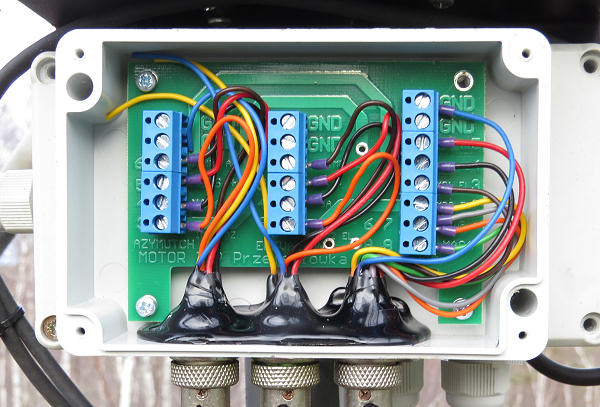
As you can see there are three cables feeding into the enclosure. The cable on the right supplies power and sends back the encoder pulses. In my system this is where the three separate 2-core shielded cables are connected. The cable in the center connects to the hall effect sensor in the Elevation drive and the cable on the left connects to the Hall effect sensor in the azimuth drive.
Internal connections are all made via terminal strips. The easiest way to install the new board is to disconnect the three cables coming into the unit (after first noting and labeling then so you put then back in the right place later). Then the entire assembly can be removed. This is best done my removing the 4 screws which attach the lid on the housing behind the senor housing (this second box contains the DC power connections to the motors). The sensor electronics housing (attached to the lid of the motor connector housing) can then be removed and worked on indoors.
After carefully noting which color wires attach to which terminal strip positions and taking a photograph just to be sure(!), the wires can be disconnected from the terminal strips. Then the 4 screws holding the board to the housing can bee removed and the PC board itself can be removed.
The new PC board an then be installed, and the connections remade as shown below:
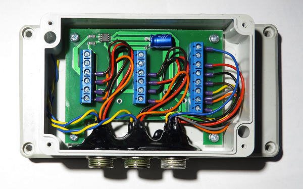
This is a fairly simple process, but double check that you have the wires connected correctly! One thing that's not immediately obvious is that is that on the terminal strip on the right, the second connection from the bottom is BOTH a grey AND an ORANGE wires. I believe these are the +V power connections. All of the other connections are one wire to each terminal position.
Then re-install the assembly on the rotor housing, reconnect the three cables (to the correct connectors!) and the job is done.
So what do the pulses actually look like? During rotation, each Hall effect sensor generates a continuous stream of symmeterical square wave pulses in quadrature (90 degree phase difference). The frequency of the pulses depends on the rotation speed of the motor. Rotation direction is given by the relative position of the two quadrature pulses. For more on Quadrature encoding see this simple explanation. Below is an oscilloscope screen capture of the two pulse streams from one of the encoders.
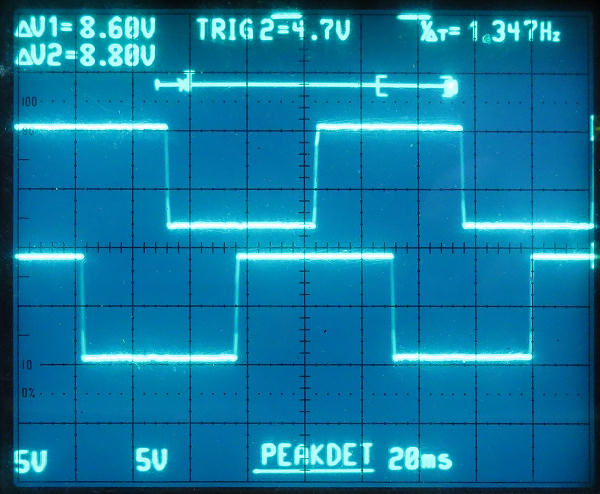
You can see the two square wave pulses, 90 degrees apart. In this second image you can seethe output from both channels for a 1 degree rotation.
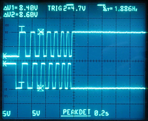
For the RAS/HR there are eight pulses per degree. The frequency of pulses changes over time due to the acceleration of the motor. If the pulses don't look quite square it's an artifact of the storage scope sampling and sweep rate. There's what a pulse looks like with the motor running at full speed and a higher sampling rate:
In general the pulses from the encoder arrive at the controller with a farily fast rise time as shown below:
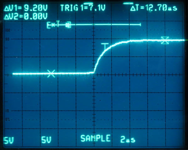
Full rise time looks like about 6mS from this trace. The fall time is similar. I did notice a small glitch ahead of the pulse on one line with the antenna moving in one direction and this is shown below"
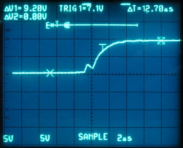
You can see there's a small peak (of about 2v) which occurs just as the main pulse starts to rise. If not properly conditioned, this could give rise to unwanted counts. However the MD-02 controller seems to deal with this glitch without a problem as far as I can tell. I saw it on my system, but it may not be typical.
Will the new electronics eliminate pulse count errors (calibration drift)
This is really difficult to say. Certainly the pulses look good, even with 25ft of individually shielded cables, plus another 50ft Serial extension cable. In operation (with the shielded cables) I can run several moon pases (moonrise to moonset) without detecting any calibration errors due to missed or miss-interpreted pulses. I've run the antenna system for a few months now, with use every day or two and I have not seen a calibration shift. This does not mean it will never miss-count pulses, but it certainly does not appear to be an issue that occurs frequently.
If calibration changes it's hard to say what is causing it. It could be due to a missed pulse. It could be due to noise on the individual lines from the sensor. It could be due to pulse detection hardware or software in the controller. I have not found any details of the controller (hardware of software) that could be analyzed.
If you wait long enough and operate the system often enough, just about any incremental encoder system is going to lose calibration. That's why many mechanical systems (and even many quadrature decoder chips) have provision for calibration via an "index" position. The is basically some sort of sensor (micro-switch, optical interrupt) which is used to calibrate an initial, known, position. All measurements are then made against this, accurately known, initial reference position.
The SPID rotor systems don't have any built in indexing system, so eventually they will almost certainly go out of calibration. It's intrinsic to any pulse counting system. How long that takes depends on the individual installation and conditions of use. It might happen in a week, or in a month or it might be a year or more before recalibration is needed. During the day, and assuming the antenna can see the sun, calibration on Sun Noise can be done. You adjust the antenna position for maximum sun noise, then set the controller to display the known position of the sun at the time (WSJT/X provide that information in the Astronomical data window). But the sun isn't always visible and moving the antenna position around looking for a signal peak can take some time.
I have an optical index position reference system (see https://bobatkins.com/radio/EME_antenna_aiming.html which I use to index the incremental encoder system of the SPID rotor. I have a laser fixed to the dish. When the dish is at a given AZ and EL setting (in my case, at the moment, it happens to be 195 degrees azimuth and 17 degrees elevation), the laser illuminated the center of a small target. If I move the dish so that I see the beam in the center of the target, I can set the SPID controller to those known AZ and EL value and it's then calibrated.