.jpg)
A Better(?) Rx Probe for Septum Feeds
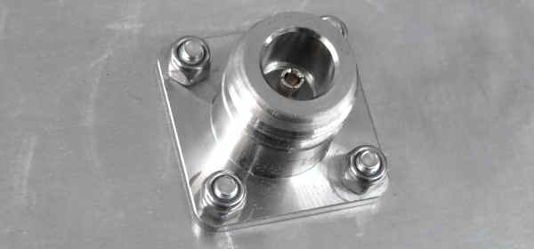
A typical septum feed - whether home-built or commercial - has an Rx probe attached to a female N-type socket mounted on the feed. Several improvements can be made to this arrangement. The main issues are:
- It isn't adjustable for the best match. To tune it, you have to remove the probe from the feed, change its length, remount it, and measure the match (SWR or S11) - ;then repeat until it's right. Alternatively, you can add a tuning disk to the rear wall of the feed.
- It uses an N connector, while most relays and LNAs use SMA connectors. This means adding an adapter or using a non-ideal cable/connector assembly that may introduce VSWR issues - especially if it's a budget connector from China.
- It requires a connector to launch the signal into a length of coax. Connectors can be lossy.
All three issues can be addressed with a modified design that uses a sliding probe directly attached to semi-rigid cable, with just one connector that goes straight to the isolation relay. Remember: every 0.1 dB of loss ahead of the LNA adds 0.1 dB to the system noise figure. For low-noise systems, a 0.1 dB increase in noise figure can reduce the SNR of a signal on a typical 23 cm EME system by about 0.5 dB, due to the rise in background noise.
I was testing an OK1DFC "short septum" feed on my extended 1.5 m cooker dish and wanted to minimize losses ahead of the LNA, as well as gain the ability to easily tune the port (this feed has no tuning adjustment screws). I've used this technique on other feeds before, and it works well.
The Mechanics
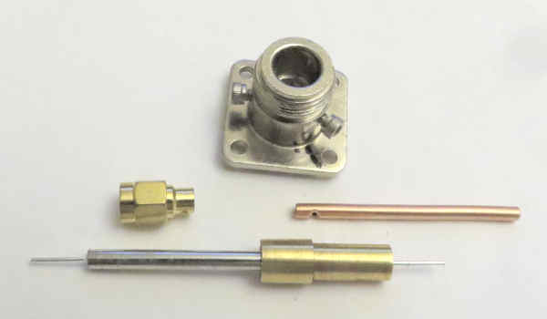
There are many ways to do this, but the easiest method - if you're replacing an N-type female socket - is shown below. Start by taking a female N socket and removing the center pin and insulation. You may need to file down the lip over the insulator on the back of the connector first, but then you should be able to push the internal components out of the housing. This leaves a strong metal tube with a flange that matches the existing mounting bolts.
Next, you need a short piece of brass rod that just slides into this N connector housing. This rod should have a center hole through which you can pass a short length of 0.141" semi-rigid coax (UT-141 or RG 402). The hole can be drilled with a #27 drill (0.144"). A 3.6 mm (0.142") bit may be too small, and a 9/64" (0.141") bit will also be too small and will need filing out to allow the coax to pass through.
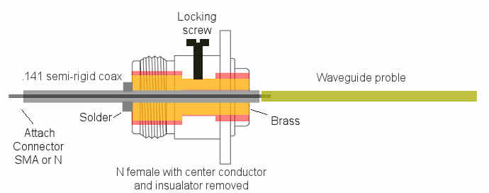
The short brass adapter can be machined to size if you have a small lathe, or you can use a standard rod size (e.g., 1/4" or 5/16") and, if necessary, drill out the N connector housing to match. In the N socket I used, the through-hole had a minimum diameter of 0.275", so 1/4" rod passed through easily - a bit too easily for a secure assembly. To secure the brass tube in the housing, drill and tap at least one 4-40 (or similar) threaded hole in the side, as shown in the drawing above. Tightening screws directly onto the outer conductor of hard line may not be a good idea; if it distorts the line, it could cause a mismatch and increase loss.
A suitable length of probe is attached to the semi-rigid coax so that it extends into the waveguide. For this septum feed (short OK1DFC 23 cm septum) on 23 cm, that was about 45 mm of 3/16" copper rod. The other end of the short coax section (loss of 0.141" hard line at 23 cm is about 0.01 dB per inch) is fitted with the appropriate connector - typically SMA. If using an SMA connector, use the coax's center pin directly rather than soldering on the supplied pin. If you won't be connecting and disconnecting it often, this minimizes loss and mismatch.
The probe can easily be tuned by monitoring the SWR or S11 at the input connector while sliding it slightly back and forth to change the probe length inside the waveguide. If you're within the adjustment range, you should find a position where SWR and/or S11 are minimized. Then lock everything tightly in place with the locking screw (see diagram above).
Here's a picture of the finished assembly feeding into the opened-up N-type socket:
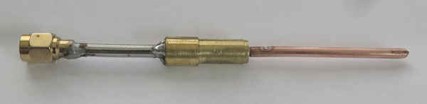
You can bend the cable to more easily attach a low-loss isolation relay, but make the bend over a circular pipe to keep it smooth. I'd suggest a minimum bend radius of 0.25" when using proper tube-bending tools (or carefully and slowly by hand using a form). If you see any deformation of the outer jacket, throw it away and start again.
Here's a picture of the finished assembly. The soldering isn't very neat, but it doesn't have to be - since its only purpose is to secure the coax in the brass barrel.
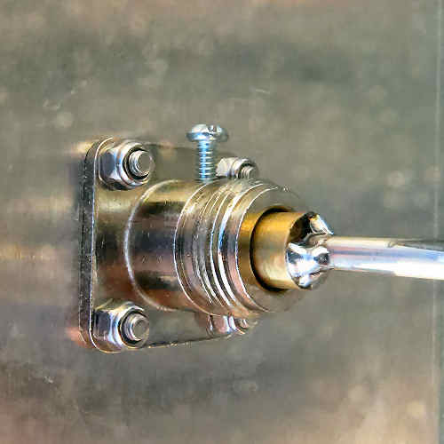
This gives you an easily adjustable, low-loss Rx probe that connects directly to your isolation relay without the need for additional adapters, and with only one connector (coax to relay).
You could also do this with 0.25" semi-rigid hard line for the TX port (or the Rx port), though on the TX port losses are less critical.
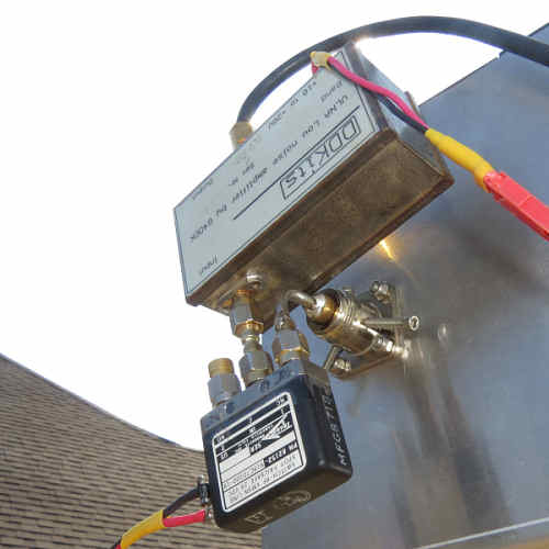
Here's another picture of the Rx port assembly with a 90° bend in the line coupling to the isolation relay. Before and after bending, the performance of the straight and bent versions looked identical. Ground (50 O) noise measured 8.11 dB at an ambient temperature of 30 °C. Sun noise was measured at about 9.5 dB at a 10.7 cm SFU value of 94. This is equivalent to about 11.5 dB at an SFU of 150, or about 10.6 dB at an SFU around 120, as measured on my extended 1.5 m cooker dish using both narrowband audio and wideband SNR systems.
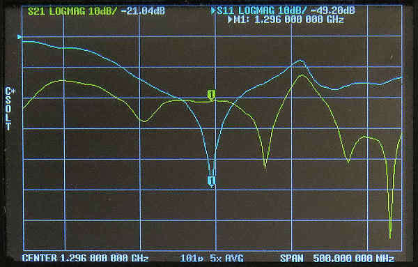
Finally, here's a VNA measurement of S11 and S21. S11 shows the return loss of the feed, which is –49 dB, or an SWR of 1:1.007. S21 (port-to-port isolation) measures 21 dB. This was a bench test; the system was retuned when on the dish. The match wasn't quite as good but was still better than –30 dB (1:1.06).
Does It Make a Difference?
The question is whether this Rx probe system gives you better reception than a standard N connector. The answer is "maybe." It all depends on how well you build it and how bad your original system was. If you start with high-quality connectors and couplers, good connections, good components, and everything is tuned correctly, you might not see much difference. All I can say is that I use this system on both my 3.1 m dish and expanded 1.5 m cooker dish, and it seems to work well. It's easy to tune (using a nanoVNA) and appears to be low-loss.