.jpg)
10Ghz EME rx System - picture and plots
On this page I have some pictures of my 10GHz EME RX system and some off-air plots of signals.
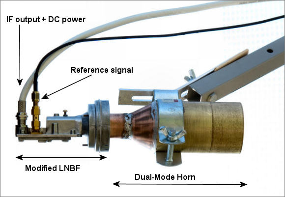
The first image shows the LNFB with a 10Ghz dual-mode feed horn designed for an f/d of 0.75 spliced on. The idea here was that it might produce more efficient illumination of the f/d 0.75 offset fed dish, though in practice it seemed to make little difference.
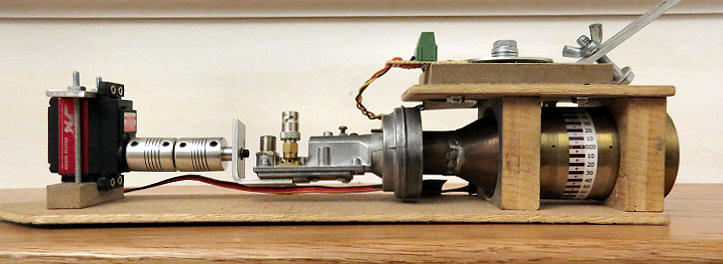
Below is the same feed mounted so that it can be remotely rotated by a servo motor (on the left) to compensate for geometric polarization offset:
Lacking any small tracking mounts, I decided to try mounting my small 10Ghz dish (inverted) in the center of my 3.1m 1296 mesh dish. The tracking is good enough to follow the moon, one Az and El are recalibrated for the offset dish. Not an ideal system, but workable.
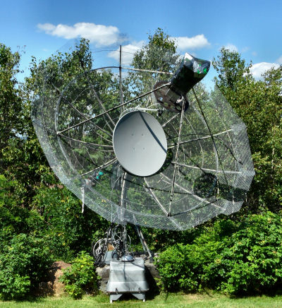
The beam from the inverted dish just misses the 1296 feed system. One of the feed support arms does cross the beam. In this position the beam is close to horizontal (0 degree elevation). For maximum moon elevation with the offset 10Ghz dish, the big dish has to go past 90 degres elevation (which it can do). Obviously the 10Ghz dish has to be removed for 1296 operation (though I could probably still get some sort of a signal out with it in place!).
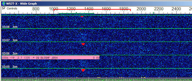
Here's a screenshot of the DL0SHF 10Ghz beacon. On the odd minutes it's 25s or so of FSK CW, followed by a 5s of carrier. Then at the start of the next (even) minute a QRA64D message starts which lasts about 48 seconds. At the (odd) minute the CW starts again.
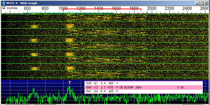
The CW tones are so broad due to libration spreading. With the radio tunes to 10368.240000 the lower CW tone should be centered at 600Hz and the upper tone at 1000Hz. The base frequency of the QRA64D signal is at the same frequency as the upper tone, i.e. 1000Hz.
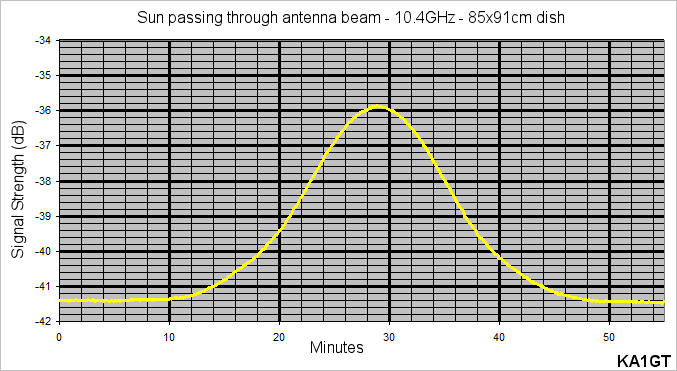
The plot below was taken as the sun drifted through the antenna pattern (85x91cm offset dish). Sun noise measures around 5.5dB based on this trace.
Here's a sun and ground noise measurement. The dish was first pointed at cold sky, then it was peaked on the sun. Following that it was moved off the sun by 1 degree, then my 2 degrees, then by 3 degrees and finally it was pointed down at the ground.
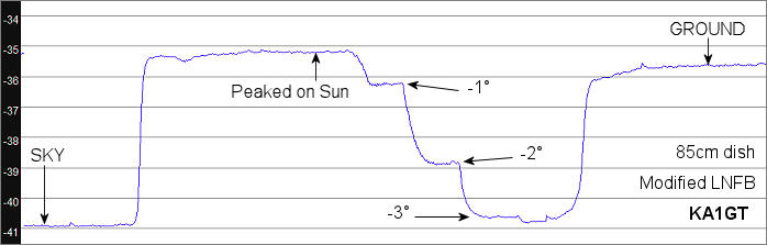
Cold Sky to Sun noise is around 5.8dB, with a 1dB drop when the dish was 1 degree off the sun and about a 4dB drop when 2 degrees off the sun. At 3 degrees off the sun it's pretty much down to the Cold Sky level. This means that if you want to be less than 1dB of the peak and you are manually pointing an 85cm dish, you probably want to plan on updating it every 5 minutes or so, initially pointing it just ahead of the sun or moon and then letting your target drift though the pattern. With a 1.2m dish you would need to update more often. If you updated every 5 minutes with a .85m dish, you would have to update every 3.5 minutes with a 1.2m dish. Cold Sky to Ground noise is around 5.25dB, suggesting the system noise figure may be the 1.2 dB region. The measurements made using a FunCube pro+ SDR dongle as the IF receiver and SpectraVue software.
Finally here's a moon-noise trace. Moon noise with an 85cm dish is not strong, but it is quite clearly detectable and I measure it at about 0.18dB from this trace.
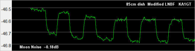
A signal this weak is not very useful for actually peaking the dish on the moon, but, in the absence of any EME signals, it can be used to verify that tracking is working and that the antenna is seeing the moon.
Update: After some tweaking of the dish and feed, I have seen up to 0.3dB moon noise at times (perigee). With this level measured in a 90kHz bandwidth, it is possible to peak the dish on the moon.
I think these images show that with a small dish and a slightly modified LNBF (with a GPS referenced LO signal), you can build a system capable of seeing and decoding 10Ghz EME signals. So far, mostly listening during a couple of contest weekends, I've copied and decoded the following stations (in alphabetical, not chronoligical, order):
- A21EME
- DC7YC
- DF1OI
- DF1SR
- DJ7FJ
- DL0SHF
- DL3WDG
- DL4DTU
- DL7YC
- F6BKB
- G4RFR
- HB9DUK
- HB9Q
- IK0HWJ
- K2UYH
- M0EYT
- OZ1FF
- OK1KIR
- OK2AQ
- OZ1LPR
- PY2BS
- RA3EME
- S57RA
- SP6JLW
- SZ1LS
- UA4AAU
- UA5Y
- UR5LX
- VE4MA
- W3SZ
- W5LUA
The smallest of these stations was probably the A21EME Dxpedition to Botswana who were running 50W to a 1.5m dish. They decoded at -22 on QRA64. An equally small station was DL3WDG who was using only a 1.2m dish, with around 75W. He decoded at around -19 using Q65-60E. Going from a 0.85m dish to a 1.2m dish should increase signal strength by 3dB. A 1.5m dish should increase signal strength by 5dB and a 1.8m dish by 6.5dB.
Absolute minimal system
So what's the absolute minimal system you need to see/copy a 10Ghz EME signal? That signal would most likely be DL0SHF since it's about the strongest station you are likely to hear and it's there every night for most of each month. Well, I have copied and decoded DL0SHF with the folling system.- 18" (47cm) offset fed dish
- LNFB (with waveguide tuning screws and connection for external LO)
- Unstabilized (XO based) LO source (in shack)
- No dish moon tracking (tracking turned off for 10 minutes)
18"dish, XO based LO, No Doppler tracking, DGRD=-2.1, Doppler Spreading = 163HzUnder these conditions, it was possible to decode the QRA64D transmission from DL0SHF, even at lunar perigee and with spreading around 160Hz. The signal was weak (-20), very hard to see (though the FSK CW transmissions were just visible). You have to be on frequency (not easy with an unstabilized LO), pointed at the moon and polarization has to be correct (DL0SHF is vertically polarized, but there will be a polarization offset which WSJT-X shows is the astronomical window). So you can do this but it is not easy if you have never looked for a 10Ghz EME signal before. The Rx system isn't very sensitive, so everything else (frequency, aiming, polarization) has to be correct. For QRA64D, you will also be decoding a signal you can't see on the waterfall. I would not really recommend starting out like this. Though it's a very cheap and fairly simple system, you will need a lot of luck to find the beacon signal. You have to be on frequency. You will not find it by "tuning around". If you are close you might see it on an SDR with a wide display. It can be seen on the wide graph of MAP65. Note MAP65 does NOT decode QRA64D, even though there's a menu option for that mode. That part of the code was not implemented. You need WSJT-X.
UPDATE: The DL0SHF beacon currently uses Q65-60E modulation, which the latest version of MAP65 can decode.